Injection Molding Simulation
DIGITAL DEVELOPMENT CHAIN – With the help of the injection molding simulation, the process of the injection molded component is analyzed before a real tool has even been manufactured. Thus, problems that would arise during the process can be identified. Appropriate measures can be taken, for example, to avoid air traps, detect weld lines and move them to non-critical areas, as well as analyze the fiber orientation. Since the filling process greatly affects the production cost, the early simulation can improve the economics of the product.
Introduction to injection molding simulation
Injection molding simulation covers the main part of the manufacturing process of an injection molded component, starting with filling the tool with the melted polymer, through the packing and finally to the cooling phase of the solidified component. The aim of this section is, to give an overview of the individual phases and work steps of an injection molding simulation.
In general, a typical injection molding simulation consists of three steps:
- Pre-processing phase
- Execution of the numerical simulation
- Post-processing of the results for visualization, parameter extraction and optimization
Pre-processing
The pre-processing phase starts with the import of the three-dimensional component geometry from CAD, which defines the essential part of the volume to be filled. This volume is then discretized, i.e., divided into small and contiguous areas. Essentially, 3 different methods are mostly used:
- Mid-plane modeling (2.5D approach)
- Surface meshing (Pseudo-3D)
- Real 3D meshing
With the 2.5D approach, the thin-walled component volume is converted into a so-called mid-surface model and only this mid-surface is meshed with 2D elements. The flow cross-section or the wall thickness is described directly by assigning it to a 2D element.
With surface meshing (pseudo-3D), the entire thin-walled component surface is meshed with 2D elements. The wall thicknesses are automatically calculated from the distance between opposite elements. The advantage over mid-plane modeling is the significantly lower manual effort involved in generating the mesh and the better description of the wall thicknesses. On the other hand, there is the disadvantage of the higher computational effort, since both surface sides of the thin-walled component must be meshed.
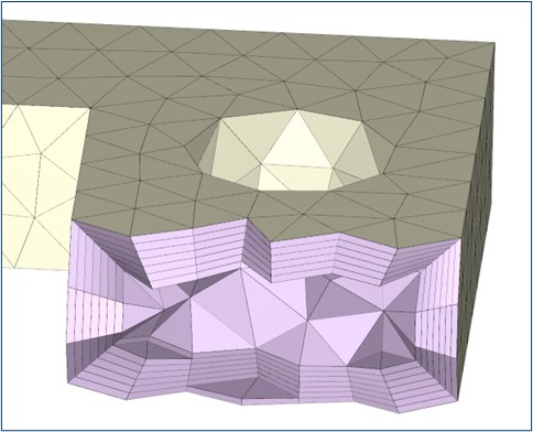
With 3D meshing, the component is meshed with volume elements (mostly tetrahedron or hexahedron), whereby so-called boundary layers are generated on the component wall to achieve a high level of calculation accuracy. However, the calculation effort of this method is the highest, since the wall thickness must be finely meshed to describe the flow of the polymer melt with sufficient accuracy. In addition to the component, all relevant elements that influence the process and quality are modeled and networked. These are e.g., tool inserts, cooling channels and runners.
 Figure 1 - Tetrahedron mesh with 7 boundary layers
After the meshing procedure, the material descriptions for the polymer, the tools and the cooling fluids are selected from a library. For the final preparation of the analysis, the process parameters like injection time, holding pressure time, holding pressure level, cooling time, melt temperature, mold temperature, cycle time and so on as well as the numerical solution scheme will be specified.
Execution of the numerical simulation
In the numerical simulation, the governing equations (mass, momentum and energy) are solved using the previously defined procedure and the results will be transferred to the post-processing module.
Post-processing
During the post-processing phase, the results of the numerical simulation are processed and presented in the form of graphics (vector plots, contour plots, etc.), videos or data tables to clarify the following points:
Can the component be filled evenly? Is the required cycle time achievable? What pressure is required? Are the changes in the cross section acceptable or do they impede even filling and lead to unacceptable pressure increases?
Sink marks can occur in areas with high accumulations of material because of the uneven shrinkage there. On the one hand, they are visually undesirable, and on the other hand, they can also impair the function of the component.
Air traps should be avoided as far as possible, as they can negatively impact the component's function. Care must be taken to ensure good mold ventilation.
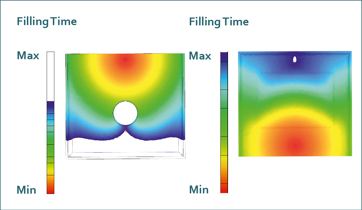
Weld lines arise when several flow fronts are brought together again. They are generally not beneficial but cannot always be avoided. However, they can be shifted to non-critical areas by means of design changes and adjusted process parameters, so that they do not impair the function.
 Figure 2 - Weld line (left), Air trap (right)
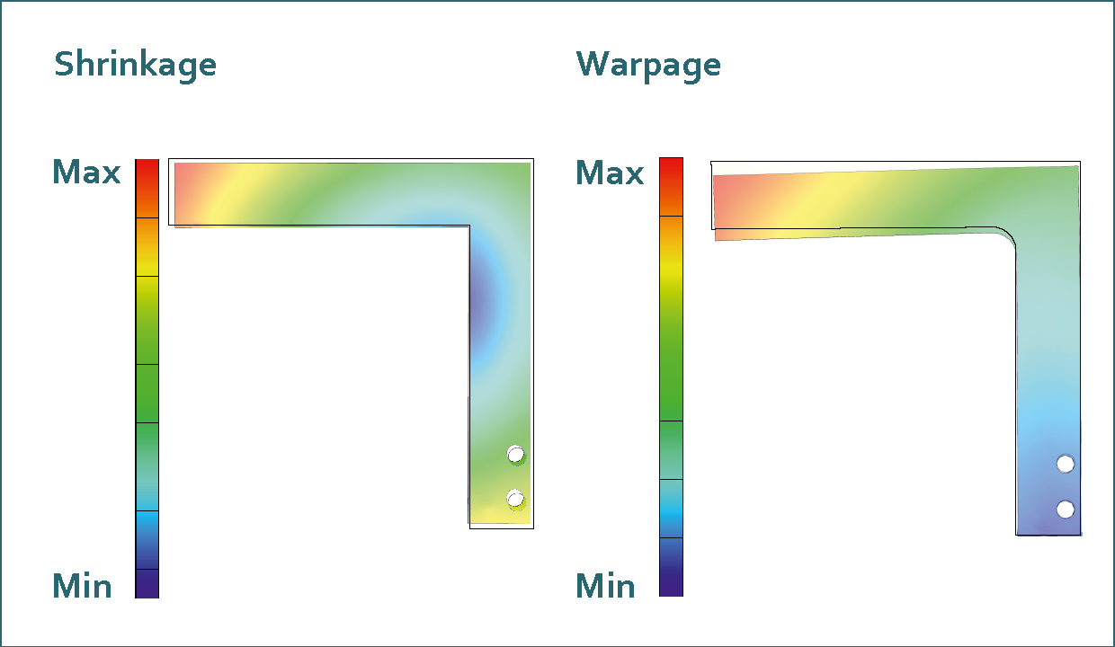
The cooling process of the polymer melt causes shrinkage and sometimes also warpage. Shrinkage cannot be avoided and is already considered during component and tool design by changing the dimensions accordingly. In post-processing, contour plots are often used to visualize it. A warpage analysis can also be carried out using the filling simulation software and provides initial indications of the component deformation to be expected because of the cooling process.
Depending on the results, optimization iterations are performed until the desired part quality is achieved.
 Figure 3 - Shrinkage (left); Warpage (right)
About the author:
Tobias Tönz has been working as a "Senior Process Technology Expert" at Sulzer Mixpac and medmix Switzerland AG for 17 years. His main activity is the design and simulation of products manufactured by injection molding. Furthermore, he focuses on the design of injection molds and machines to create the basis for optimal manufacturing processes.
