Structural mechanics Simulation
DIGITAL DEVELOPMENT CHAIN – The finite element analysis (FEA) is an established procedure for the calculation of structural, thermal, acoustic and coupled problems. With this method, it is possible to examine the load situation of a product virtually before a first prototype has been produced. In this way, a design version can be analyzed realistically and, if necessary, optimized by constructive adjustments. In the best case, only a few and necessary tests are carried out later. Thus, the application of the finite element analysis can lead to a reduction in development costs.
Introduction to structural mechanics simulation (finite element analysis)
The finite element method is a numerical approximation method for any field problem, i.e., for problems that can be described by partial differential equations. In structural mechanics, it can be used to calculate almost all conceivable mechanical load situations. The aim of this section is, to give an overview of this analysis method during the product development process of mixing and application systems.
In general, a typical finite element analysis consists of three steps:
- Pre-processing phase
- Execution of the numerical simulation
- Post-processing of the results for visualization, parameter extraction and optimization
Pre-processing
The three-dimensional structure is usually created using a CAD program (Computer Aided Design). After importing this geometry into the pre-processor, the preparatory work for the analysis takes place:
Geometry simplification and processing, dimensionality: Among other things, geometric details that are not important for the intended analysis will be removed. This can be e.g., radii, holes or later unloaded regions. Furthermore, it is decided whether a 3D, 2D or axisymmetric analysis should be carried out. The aim of this work is to reduce the complexity of the model, only take the essential details with it and thus ultimately reduce analysis time and costs.
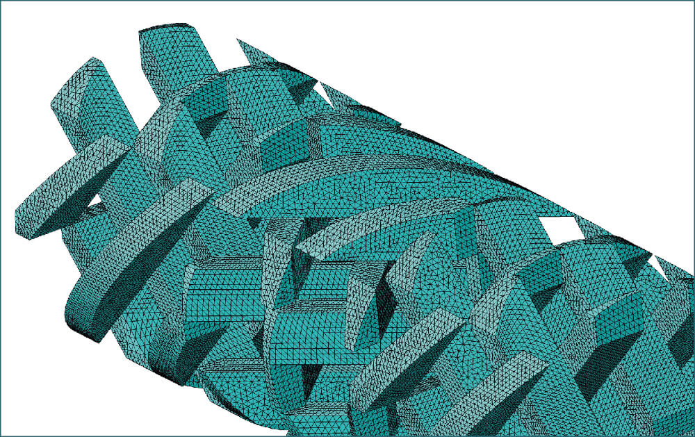
Discretization: Now the part geometry is divided into small finite elements connected at the nodes. The elements differ in the dimensionality, the number of nodes and the internal descriptions and are selected by the user based on the specific calculation requirements. Depending on the dimension of the problem to be described, bar elements (1D), shell elements (2D) or volume elements (3D) are used. The usual analysis programs have a large number of different element descriptions at each dimension. For example, to capture curvilinear element boundaries, 2 nodes at one side of an element are no longer sufficient. It must be inserted at least one more node in the middle between 2 corner nodes. The number of nodes per element side influences the internally used so-called approach functions, which is the internal mathematical description of each element, but also the calculation costs.
 Figure 1 - 3D Finite element mesh (Tetrahedron elements) of a static machine mixer
Material assignment: In this step, each element is assigned a material property. In the simplest case of a static, linear-elastic analysis under dead-load, these are the density, the modulus of elasticity and the Poisson's ratio. If a more complex behavior is to be represented by the calculation, then additional parameters, such as e.g., stress-strain curves or time-dependent data can be made available.
Boundary conditions and external loads: The term boundary conditions means e.g., the fixation of a beam. This is realized in the model by preventing all movements of the corresponding nodes. The external loads are either applied to the corresponding nodes (forces, moments) or element surfaces (pressure loads).
Execution of the numerical simulation
After the finite element model has been defined in the pre-processor, a system of equations is created from it, transferred to the solver and then solved by it. The previously unknown quantities (displacements, section and reaction forces) are now available as result data in an internal program database and can be passed to the post-processor together with the calculation model.
Post-processing
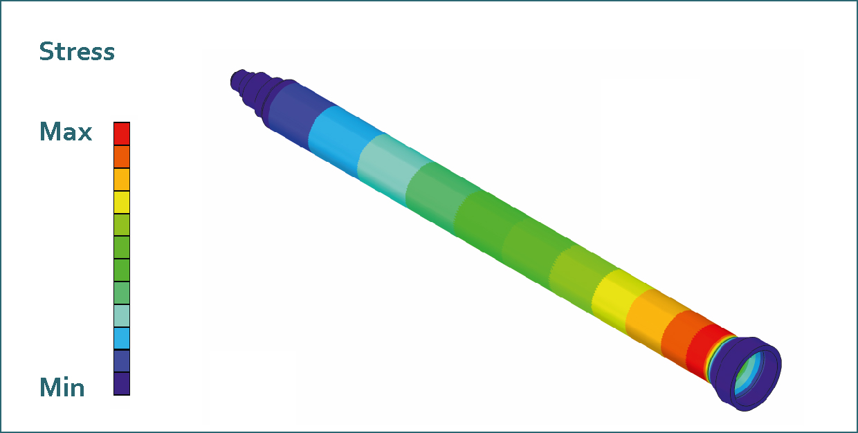
During the post-processing phase, the results of the numerical simulation are processed and presented in the form of graphics (vector plots, contour plots, etc.), videos or tables of values. Similar to pre-processing, this work is mostly controlled directly by the user. For instance, the following questions can now be clarified:
Are the calculation results plausible? For this purpose, rough calculations regarding the magnitude of deformations, stresses or strains are carried out and compared with the numerical results. For this purpose, so-called manual calculations are often performed using methods from classical mechanics.
Does the component fail under the applied load? Is there enough safety margin? For this purpose, e.g., in static analyses, the calculated deformations, stresses and strains are compared with allowable values and evaluated. For instance, in an analysis of a mixer housing under internal pressure, these would be the maximum radial expansion, the change in length due to the cover force or circumferential stresses and strains.
What optimization potential is there? Since the analysis results provide information on critical regions, the designer can be given specific suggestions for optimization, such as additional radii to reduce notch stresses or increasing the wall thickness to reduce deformation or stresses. On the other hand, it is also possible to provide information regarding a reduction in wall thickness if the calculated deformation or stresses are so small that there should be an excessively high safety margin.
 Figure 2 - Maximum principal stress of a mixer casing during application
About the author:
Thomas Zacharias has been working for a total of 18 years in various Sulzer divisions and now as "Senior Technology Expert" at medmix Switzerland AG. His main activity is to ensure and optimize the structural integrity of high-precision application and mixing systems. This is done by applying analytical and numerical calculation methods as well as developing individual experimental test methods.
